Powered by Blogger.

GLBP Gateway load balancing protocol

GLBP or Gateway load balancing protocol is used for load balancing and gateway redundancy in a network. Instead of giving actual MAC addressed with the default gateway, the GLBP group provides virtual MAC to the requesting hosts, which can be used further in creating network redundancy. Some of the main components of GLBP are:

  • Active Virtual Gateway
  • Active Virtual Forwarder
Active virtual gateway takes care of all virtual MAC assignments in the network. In case of its failure, active virtual forwarder with second highest priority takes its place.

 Quick Facts:
  • GLBP uses 224.0.0.102 UDP/3222
  • GLBP default Hello interval is 3 seconds
  • GLBP has virtual MAC 0007.b4xx.xxyy with xx being group number and yy being forwarder number
  • GLBP allows up to 4 virtual MAC address per group
  • Elected Active Virtual Gateway (AVG) assigns/revokes virtual MAC to/from group members
  • Each gateway is an Active Virtual Forwarder (AVF) and answers own ARP request
--to be continued--


Address Resolution Protocol (ARP)

Introduction:


Okay, you are sitting on a LAN Network and communicating with different hosts without any issue. But how does your computer know about other hosts on the LAN or anyone host on the Internetwork? The mystery behind all these operations is ARP. Address Resolution Protocol gives us a facility to resolve IP addresses into the corresponding MAC addresses.  When a computer wants to send data to some unknown host on the network, which MAC address is not known and all the info that computer has is just an IP address, ARP is used to resolve its L2 address. All this data is maintained in an ARP table on each host locally, Routers and Switches also maintain an ARP table.

Quick facts about ARP:

  • ARP is defined by RFC 826
  • Acronym for Address Resolution Protocol
  • Used to resolve IPs to MAC address
  • ARP is not a secure protocol, can be bypassed via ARP spoofing (Man in the middle attack)
  • InARP or Inverse ARP is used to resolve L2 addresses into an L3 address (mostly used in ATM and FRAME Relay Networks)
  • ARP stuffing is used for L2/L3 address resolution in consumer electronics devices

In order to check an ARP table that is maintained by a home PC or computer host, just type arp –a on command prompt, the output is something like:


Now just imagine a local LAN, on which a host wants to ping an unknown host. In the first step it will send an ARP broadcast to all hosts on the LAN and will enquire about the IP address. A sample capture of an ARP broadcast capture in packet tracer is as follow, PC2 wants to communicate with PC4:


As the MAC is not known, it’s using a broadcast address in L2 and the packet is sent to all hosts on LAN. Now what happened on PC4?


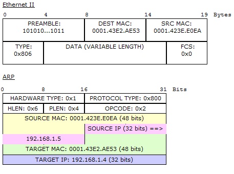
The ARP request`s target IP (192.168.1.5) got matched with 192.168.1.5, so this host will reply to PC2, so the magic that happens next is:


The address has been resolved to corresponding MAC address as can be seen in Out Layers, so in the last stage:


As you can see in above ARP packet at the source host PC2, the pinged L3 address of PC4 has been successfully resolved to its corresponding MAC (Hardware) address. Packet tracer is one of the best tools to see all the action on data packets in a real time network. To check ARP table on a router, use show ip arp command.


ARP due to is its open nature is susceptible to attacks. The most common attack on ARP packets is ARP Spoofing or Man in the middle attack. In such an attack, a hacker responds to ARP requests in disguise of the requested L3 address. One most recent example of ARP spoofing attack was carried out by Iran on an American drone, which was hacked and landed in Iran by Iranian Defense forces. Same sort of experiment was carried out in a US University in which ARP spoofing was used as an attack mechanism on Drones, and it was quite successful. DOS (Denial of Service) attack can be carried out very easily on the electronics devices which are using ARP stuffing, so a hacker can easily jam all the surveillance system of some big corporation J


Some addition NAT Services


We can adjust timeout values for different sort of packets in NAT is follow:


Some special NAT services that we can enable are for SIP and other communication protocols:


These services are needed to be enabled as we can’t modify IP header value in data packet in some special applications SIP, H.323 etc.


SNAT: Statefull Network Address Translation:

Okay, no network is ideal when it comes to 100 % up time, to avoid network failure; we use redundancy in our designs. So how it’s done in NAT? For this purpose we use Statefull NAT. in SNAT we create a group of our NAT IP addresses. The active Translator IP continuously exchanges the route maps and NAT entries with the Redundant NAT IP, in case the active IP translator fails, the redundant IP Translator take charge immediately. It is better represented in below network Topology:


I think that’s enough! We have had quite a discussion on NAT. NAT is one of the coolest protocol, which has really helped in preservation of the IP address space. If there was no NAT, we would be using IPv6 now!

 A little recap of what we have discussed so far:

  • Dynamic NAT
  • Static NAT
  • Dynamic NAT with PAT
  • Practical implementation of NAT-3 Steps
  • NAT Debugging
  • NAT translation timeout control
  • Common issues with NAT and its troubleshooting
  • NAT special services
  • SNAT or Statefull NAT

I would request you to please implement the above mentioned NAT topologies and practice all the NAT related configurations. As Practice is the key to master NATING! 


Network Address Translation V


In this part of NAT we will discuss the last common type of NAT, which is Static NAT. we will also discuss some of the features and special services on NAT. The discussion ends with a brief overview of SNAT (state-full Network Address Translation)

Static NAT:

Now let’s suppose we have our email server on 192.168.4.1/24 on R1. Suppose we want to create a static NAT entry to for SMTP (simple mail transfer protocol) on this server, so that it can communicate with the outside world and its SMTP service should be accessible from outside as well.

 It is achieved by enabling Static NAT on R2; we just need to issue the following command in global configuration mode:

ip nat inside source static tcp 192.168.4.1 25 interface Serial1/0 25


Port 25 = SMTP port or email server port

On Port 25 if any packet is received on our Router R2 interface serial 1/0, it will be forwarded to our SMPT server 192.168.4.1 and vice versa.  So if we see our NAT translations, we will see a permanent static NAT entry for TCP port 25 in it:


This entry will not expire from the NAT table after translation timeout.  All dynamic entries are deleted from the NAT translation table after translation timeout. As we have already discussed, static mapping is mostly use for server accessibility from outside the local network. 
Please remember, STATIC NAT is both way NAT i.e. we can use it for accessibility from outside our network.


Troubleshooting NAT:

Some of the points we need to keep in mind while troubleshooting NAT:

  • Check they dynamic pools, they must contain correct IP ranges.
  • Check if static IPs are overlapping with the IP pool configured.
  • Check if ACL is correctly defined. The addresses to be mapped are properly specified no address left out.
  • Proper inside/outside NAT interfaces are configured.
 -- to be continued --

Network Address Translation IV


In this part of our NAT discussion, we will implement NAT with overload or PAT (Port Address Translation) on our R2 router.

NAT Overload (PAT):

Now we are going to implement NAT overload on R2, so we need to add overload to the end of ip nat command like:

First we will clear all IP NAT translations (that were done previously once we configured dynamic NAT), by issuing the following command:

R2#clear ip nat translation *

Now we will overload the NAT by using overload key word at the end of our dynamic NAT command:

R2(config)#ip nat inside source list NAT_IPs pool Global_IP_Pool overload

To check our NAT in action, we will issue some of pings from our loop back interfaces on R1:

R1#ping 171.16.10.2 source 192.168.3.1
Successful!

R1#ping 171.16.10.2 source 192.168.3.1
Successful!

R1#ping 171.16.10.2 source 192.168.2.1
Successful!

R1#ping 171.16.10.2 source 192.168.4.1
Successful!

All of these pings were successful via NATing, to check the NAT translations on R2, we will use the following commands:

R2#show ip nat translations

//some of the output omitted//


icmp 171.16.10.53:4    192.168.2.1:4      171.16.10.2:4      171.16.10.2:4
icmp 171.16.10.53:3    192.168.3.1:3      171.16.10.2:3      171.16.10.2:3
icmp 171.16.10.53:5    192.168.4.1:5      171.16.10.2:5      171.16.10.2:5


PAT can be seen in action, in below output of show ip nat translations command:

R2#show ip nat translations

/// some of the part omitted//

udp 171.16.10.53:49157 192.168.2.1:49157  171.16.10.2:33437  171.16.10.2:33437
udp 171.16.10.53:49158 192.168.2.1:49158  171.16.10.2:33438  171.16.10.2:33438
udp 171.16.10.53:49159 192.168.2.1:49159  171.16.10.2:33439  171.16.10.2:33439
udp 171.16.10.53:49164 192.168.2.1:49164  171.16.10.2:33437  171.16.10.2:33437
udp 171.16.10.53:49165 192.168.2.1:49165  171.16.10.2:33438  171.16.10.2:33438
udp 171.16.10.53:49166 192.168.2.1:49166  171.16.10.2:33439  171.16.10.2:33439
icmp 171.16.10.53:10   192.168.3.1:10     171.16.10.2:10     171.16.10.2:10

if we want to check NAT in real time, all the action can be seen via bebug ip nat command on R2:
Once debug command is issued on R2, all the IP changes happening in real time can be seen as on R2 as follow:

R2#
*Mar  1 00:07:31.079: NAT: [0] Allocated Port for 192.168.2.1 -> 171.16.10.53: wanted 6 got 6
*Mar  1 00:07:31.083: NAT*: i: icmp (192.168.2.1, 6) -> (171.16.10.2, 6) [30]
*Mar  1 00:07:31.087: NAT*: i: icmp (192.168.2.1, 6) -> (171.16.10.2, 6) [30]
*Mar  1 00:07:31.087: NAT*: s=192.168.2.1->171.16.10.53, d=171.16.10.2 [30]
*Mar  1 00:07:31.115: NAT*: o: icmp (171.16.10.2, 6) -> (171.16.10.53, 6) [30]
*Mar  1 00:07:31.115: NAT*: s=171.16.10.2, d=171.16.10.53->192.168.2.1 [30]
*Mar  1 00:07:31.147: NAT*: i: icmp (192.168.2.1, 6) -> (171.16.10.2, 6) [31]
*Mar  1 00:07:31.147: NAT*: s=192.168.2.1->171.16.10.53, d=171.16.10.2 [31]
*Mar  1 00:07:31.179: NAT*: o: icmp (171.16.10.2, 6) -> (171.16.10.53, 6) [31]
*Mar  1 00:07:31.179: NAT*: s=171.16.10.2, d=171.16.10.53->192.168.2.1 [31]
*Mar  1 00:07:31.191: NAT*: i: icmp (192.168.2.1, 6) -> (171.16.10.2, 6) [32]
*Mar  1 00:07:31.191: NAT*: s=192.168.2.1->171.16.10.53, d=171.16.10.2 [32]
*Mar  1 00:07:31.211: NAT*: o: icmp (171.16.10.2, 6) -> (171.16.10.53, 6) [32]
*Mar  1 00:07:31.211: NAT*: s=171.16.10.2, d=171.16.10.53->192.168.2.1 [32]
*Mar  1 00:07:31.219: NAT*: i: icmp (192.168.2.1, 6) -> (171.16.10.2, 6) [33]
*Mar  1 00:07:31.219: NAT*: s=192.168.2.1->171.16.10.53, d=171.16.10.2 [33]


All this action will be seen if we issue some connectivity commands from other routers, whose packets are going through R2. It’s one of the best way to check and troubleshoot different NAT issues. Please remember, PAT (Port Address Translation) is a one way NAT, we can’t use it as a both way NAT solution.
 -- to be continued --

Network Address Translation III


In this part we are going to configure Dynamic NAT on our gateway router ( R2). We will following the previously mentioned three steps to achieve this task like: 
  • Labeling the interfaces
  • Configuring the ACL for hosts
  • Implementing the NAT from global config mode


So here we go, and you will see it’s not that difficult to implement it practically:

Dynamic NAT Configurations:

Suppose we want to configure Dynamic NAT on R2. For this purpose, we need a pool of global IP addresses that would be dynamically mapped with our local hosts. So we need to buy these addresses from our ISP J just assume, we bought the following IP pool form our ISP:

171.16.10.52 - 171.16.10.56

We will follow above mentioned three steps to implement dynamic NAT on our current network topology:
Step 1:

Labeling the interfaces:

interface FastEthernet0/0
 ip address 192.168.1.2 255.255.255.0
 ip nat inside

interface Serial1/0
 ip address 171.16.10.1 255.255.255.0
 ip nat outside

Step 2:
An ACL needed to be created for local hosts IPs that we want to translate:

ip access-list standard NAT_IPs
 permit 192.168.3.0 0.0.0.255
 permit 192.168.2.0 0.0.0.255
 permit 192.168.4.0 0.0.0.255

Step 3:
Once ACL is created, we need to configure our IP pool and dynamic NAT from global configuration like:

ip nat pool Global_IP_Pool 171.16.10.52 171.16.10.56 netmask 255.255.255.0
ip nat inside source list NAT_IPs pool Global_IP_Pool

Our pool name is: Global_IP_Pool
ACL name is: NAT_IPs

Some of the other things done on R2 are: static route to ISP and RIP:

!
router rip
 passive-interface Serial1/0 ( this commands is configured to stop RIP advertisements to our emulated ISP)
 network 171.16.0.0
 network 192.168.1.0
!
ip route 171.16.0.0 255.255.0.0 171.16.10.2
!
!

And we are done with our Dynamic NAT! that was quite easy and simple. Now some other fun commands. In order to check the IP NAT translations going on in the network, we just issue show ip nat translations command on R2 and see the result:

From R1 we ping our ISP:

R1#ping 171.16.10.2 source 192.168.3.1
We get successful ping results to 171.16.10.2. The source IP was changed on R2 during the process of pinging as we have configured NAT on R2.

Now let’s see what’s happening on R2:


Our ping request was originated from inside local: 192.168.3.1 and has been translated into 171.16.10.52 inside global address.  One other interesting command for your geek mind:


I hope after going through all of the above commands, you will have confidence in yourself and will see how interesting it is to implement.  Just remember one thing: if dynamic NAT is used, we can’t access our local hosts from outside the network, as the router will not be sure to where it has to route the packets and for this purpose Static NAT is recommended, which we will discuss shortly.

Okay, as an example, please perform some practice of dynamic NAT with following requirements:

  • The routing protocol running is EIGRP with AS # 4
  • The IP Pool Name is CORP-IP pool
  • ACL is allows only 192.168.3.0/24 network to translate
--to be continued--

Network Address Translation II


Static NAT: static NAT is a one to one mapping of internal addresses with the global IP addresses. In network design, static NAT is best if we are going to host some server inside our network and want it to be accessible from global internet.

Some of the terminology of NAT worth remembering:

  • Inside Local: the host address inside the network that we want to translate
  • Outside Local: translated address of the outside hosts, as seen inside their network
  • Inside Global: the addresses used to translate the inside addresses
  • Outside Global: addresses of outside hosts as seen on the outside
A few more terminologies of NAT:

  • Policy based NAT
  • Port redirection (one to one mapping for a single port, also called Static PAT)
  • NVIs or NAT virtual interfaces (a newer method of NAT configuration in which there is no need for inside/outside definition on an interface. NAT table is maintained on per interface basis)

I think we have covered enough of the terminology regarding Network Address translation, now it’s time to practically implement all of the above concepts for getting a strong technical grasp of above concepts.

For practical implementation of NAT on a Cisco router, follow the following three steps:

  • Designate the interfaces for inside/outside NAT
  • Define an ACL for the local host IPs
  • Implemented NAT from the global configuration mode
In VoIP packets, as it’s not possible to modify the source header, for this we had to enable some special services of NAT to support SIP or Skinny protocols etc. there are also some other issues that might arise by changing the IP in a packet as it will change the packet checksum value, encapsulated data and hence breaking the meaning of the application.

For an interesting demonstration of NAT, please check http://www.cisco.com/image/gif/paws/6450/nat.swf URL.

--to be continued-- 

Network Address Translation Part I


NAT (Network Address translation):

In simple words NAT is about IP address translation or conversion. This translation could be for two purposes
  • Translation of Private addresses into Public addresses
  • Translation of internal addresses to avoid duplication or for Topology hiding

As you know private IP addresses are not routable on the internet, that’s why we need to configure NAT on our gateways to talk to public internet domain.  The duplication of addresses can take place if we merge two organizations and they both have the same IP plan, in such case NAT is used to avoid such issues via a DNS server. As discussed in VLSM and CIDR, IP address preservation was also one of the main causes behind the induction of NAT.


NAT working:


The above diagram explains NAT in its simple form. NAT is configured on the Gateway and address translation or mapping take place here. The Global Network is unaware of the internal local addresses of our network, that’s why it’s helpful in hiding our network topology.


Types of NAT:

There are three types of NAT, mostly used in network design. 

  • Dynamic NAT
  • Dynamic NAT with overload (also called PAT: Port Address Translation)
  • Static NAT
While implementing NAT on a router, we first define an ACL (normally standard Access Control list) to define the internal IPs that we are going to translate. These addresses are technically called Inside Local addresses.  Then we apply our NAT commands in global configuration mode, specifying the list of addresses in our ACL and the public addresses in which we want to translate it. These public addresses are technically called Inside Global.

Dynamic NAT: In dynamic NAT, as the name suggest the address translation take place by allocating available Public IPs from a pool dynamically. We define a pool of global IP addresses for NAT and then this pool is associated with address local IPs for translation. The address translation works, until all of the addresses in pool are consumed and network established via it.

Dynamic NAT with overload or PAT: overloading is used to enhance the addressing capability of NAT and for this magic, PAT is used. PAT stands for Port address translation, so as the name implies, port numbers are used with local hosts. At the same time, port numbers are also used with the global inside IP. Via this association, a single global IP can be used for around 65000 addresses! This could be better explained via below chart:


Protocol
Inside Local IP : Port
Inside Global IP : Port
TCP
192.168.3.2:1723
170.16.3.2:1456
TCP
192.168.3.1:1744
170.16.3.2:1098
TCP
192.168.3.10:1764
170.16.3.2:4432

As you can see we have a single global IP, but with different port numbers. This table is maintained by router and it forwards the packet accordingly. Suppose if IP 192.168.3.2:1723 has established global connection via 170.16.3.2:1456, once any packet is received on this IP (170.16.3.2) with relevant port number, its forwarded according to the above table to 192.168.3.2:1723. You must be aware of the fact that port numbers are used by a host to establish different connections to the outside world and keep track of each established connection. Suppose a connection to web server port 80 would be like:

Inside Global IP : Port
Outside Global IP address: Port
170.16.3.2:1456
173.194.23.4:80
170.16.3.2:1098
173.194.23.4:80
170.16.3.2:4432
173.194.23.4:80


--To be continued--

Network Security, A short overview


Introduction


There is no such thing as a secure network! Once we are connected to some network, we are not 100 % safe! There is no such thing as 100 % security. Each year Million of Dollars are lost to different sorts of network exploits and vulnerabilities. The attackers and attacking technologies have become so sophisticated that at any instant we can become a victim of identity theft, our sensitive information could be stolen, our credit card could be hacked or someone can use our social security number.

According to FORTINET recent report of Cyber Crimes for 2013, “Gone are the days when when cybercrime was tantamount to teenage miscreants causing mischief in their parents’ basement. Today, as any commercial enterprise, cybercrime has evolved into a complex, highly organized hierarchy involving leaders, engineers, infantry, and hired money mules”. So Network Engineers are facing more complex challenges as the problems and systems are evolving in complexity. With each year, the number of security breaches into high profile networks are increasing, one of the recent example is in the form of Stuxnet, which attacked Iran Atomic power plant SCADA systems. Viruses like Suxnet/Duqu (a Stuxnet like virus) are so sophisticated that they can take control of the automatic industrial systems and Power Grids, hence can cause unimaginable damage. In this research paper we will cover the following areas of Network Security:
  •          Critical Infrastructure Protection
  •          Wireless Sensor Network Security
  •          Secure and Trustworthy Composite Services

A comprehensive overview of different approaches is given regarding above mentioned security methodologies. Our major focus is on Critical infrastructure Protection. In the modern world, no company can afford creating a network like Fort Knox, but if proper precautions are taken, real damage could be avoided.


Critical Infrastructure Protection

According to US Homeland Security Presidential Directive HSPD-7 CIP ( Critical Infrastruction Protection) covers all the systems that are “so vital to the United States that the incapacity or destruction of such systems and assets would have a debilitating impact on security, national economic security, national public health or safety.” Critical Infrastructure includes all the physical and virtual systems which are like backbone for a country survival, protection and progress. These are such critical elements, which are usually attacked during wars to cripple a country. A virus attack on an Atomic power plant can cause a blazing impact on a country, enough to kick back a nation in the stone age. Critical Infrastructure includes:

  • Atomic Assets
  • Banking/Finance
  • Department of Energy
  • Emergency Services/Fire departments
  • Transportation
  • Space/Logistics/Defense Industries

In the past most of the physical infrastructures were totally isolated, but advancements in technology and communications have increased the interconnectednes. This interconnectedenes has opened many new frontiers of cyber attacks and vulnerabilities never seen before. The famous DoD critical infrastructure protection model is :

  1. Analysis and Assessment
  2. Remediation
  3. Indications and Warning
  4. Mitigation
  5. Incident response
  6. Reconstitution


 to be continued... 


Static to Dynamic IPsec configuration


!
ip subnet-zero
!

!--- These are the IKE policies.

crypto isakmp policy 1

!--- Defines an Internet Key Exchange (IKE) policy.
!--- Use the crypto isakmp policy command
!--- in global configuration mode.
!--- IKE policies define a set of parameters to be used
!--- during the IKE phase I negotiation.

 hash md5
authentication pre-share

!--- Specifies pre-shared keys as the authentication method.

crypto isakmp key Chris123 address 165.228.212.83

!--- Configures a pre-shared authentication key,
!--- used in global configuration mode.

!

!--- These are the IPSec policies.

crypto ipsec transform-set rtpset esp-des esp-md5-hmac

!--- A transform set is an acceptable combination
!--- of security protocols and algorithms.
!--- This command defines a transform set
!--- that has to be matched on the peer router.

!
crypto map rtp 1 ipsec-isakmp

!--- Creates a crypto map and indicates that IKE will be used
!--- to establish the IPSec SAs for protecting
!--- the traffic specified by this crypto map entry.


set peer 165.228.212.83

!--- Use the set peer command to specify an IPSec peer in a crypto map entry.

set transform-set rtpset

!--- Configure IPSec to use the transform set "rtpset"
!--- that was defined previously.

 match address 115
 exit

!--- Include the private-network-to-private-network traffic
!--- in the encryption process.

interface Ethernet 0
 description --- Ethernet LAN ---
 ip address 192.168.0.254 255.255.255.0

 ip virtual-reassembly
 ip tcp adjust-mss 1420

!
!
ip dhcp excluded-address 192.168.0.251 192.168.0.254
!
ip dhcp pool lan
network 192.168.0.0 255.255.255.0
default-router 192.168.0.254
dns-server 192.168.0.254
lease infinite

interface ATM0
 description --- Telsra ADSL ---
 no ip address
 no shutdown
 no atm ilmi-keepalive
 pvc 8/35
  tx-ring-limit 3
  encapsulation aal5snap
  pppoe-client dial-pool-number 1


interface Dialer0
 description --- Telsra ADSL ---
 ip address negotiated
 ip mtu 1460
 ip nat outside
 ip virtual-reassembly
 encapsulation ppp
 ip tcp adjust-mss 1420
 dialer pool 1
 dialer-group 1
 ppp chap hostname tareet0@direct.telsra.net
 ppp chap password 233981
 crypto map rtp

ip nat inside source list NAT interface Dialer0 overload

ip nat inside source route-map nonat interface Dialer0 overload