Powered by Blogger.

CIDR II: A little more in depth explanation


PART II:

Suppose our ISP owns an address block: 200.24.0.0/16. What this means?

An address block comprises of different address that the ISP can allocate and sell to its customers. The IP address block 200.24.0.0/16 can represent 2^16 = 65, 536 IP addresses. Suppose from this block it wants to allocate 200.24.15.0/20 address block. So how many addresses is this in reality? Simple, 2^12 = 4096 or 16 /24s, how? The block size is /20 or in other words 255.255.240.0 so our block size can be calculated as 256-240 = 16 , this means the given /20 block comprises of 16 /24 addresses if we are considering a Class full environment.

200.24.15.0
200.24.16.0
200.24.17.0
200.24.18.0
200.24.19.0
200.24.20.0
200.24.21.0
200.24.22.0

200.24.23.0
200.24.24.0
200.24.25.0
200.24.26.0
200.24.27.0
200.24.28.0
200.24.29.0
200.24.30.0

Each address has the capacity to represent 255 addresses so 255*16 = 4096, as already mentioned above.  So if the ISP distributes these among 3 organizations named A, B, C—the distribution would be as follows:

200.24.15.0
200.24.16.0
200.24.17.0 Block size of 4, 256-4=252 so the whole block would be 200.24.15.0/30
200.24.18.0                    IPblock 200.24.15.0/30 will be assigned to the Organization A

200.24.19.0
200.24.20.0
200.24.21.0
200.24.22.0 Block size of 8. 256-8 = 248 so the whole block would be 200.24.19.0/21
200.24.23.0                     IPblock 200.24.19.0/21 will be assigned to organization B
200.24.24.0
200.24.25.0
200.24.26.0


200.24.27.0
200.24.28.0Block size of 4, 256-4=252, so the whole block would be 200.24.27.0/30
200.24.29.0                    IPblock 200.24.27.0/30 will be assigned to organization C
200.24.30.0

Believe me, by doing above process, we have cracked all the route aggregation and summarization at the Global, ISP and Organization level.

You will feel that CIDR has the same look like VLSM. Yes, it’s right to some extent. Both allow us to change the IP dynamics according to our requirements, but VLSM is invisible to the global internet. The VLSM can be felt only in our internal network topology. On the other side, CIDR is visible to the global internet. A global Internet Registry can assign any CIDR block or prefix block to any top level ISP, to a medium level ISP or to any private organization.

Okay now some interesting stuff. If you want to see all this CIDR, route summarization in action, visit MeritRADb the routing asset database online website. This website provides information related to all the routed networks and ASs on the internet up to this moment! For example if we want to dig this IP: 173.194.67.104, we will go to their website: http://www.ra.net/  and will query this IP using Query the RADb box. The output is quite interesting:

route:      173.194.67.0/24
descr:      Google
origin:     AS15169
notify:     radb-contact@google.com
mnt-by:     MAINT-AS15169
changed:    radb-contact@google.com 20121119
source:     RADB

This IP (173.194.67.104) is owned by Google incorporations!! Okay one more IP: 205.134.232.114

route:      205.134.224.0/19
descr:      Corporate Colocation, Inc.
origin:     AS17139
notify:     netops@mzima.net
mnt-by:     MAINT-CORPCOLO
changed:    noc@corporatecolo.com 20071108
source:     RADB

The above IP is somehow part of the major route shown in the RADb output. The Routing Asset Database website is one of a great place to spend your weekend time on!

Please remember that IANA or Internet Assigned Number Authority is the organization responsible for taking care of global IP address allocation and other IP related activities. 

CIDR - Classless Inter-domain Routing


PART I:

CIDR (RFC: 4632): Classless inter domain routing. In simple words, CIDR is like supernetting route summarization and VLSM at the ISP end that’s why it is called Classless inter domain routing. Confusing? Okay let us discuss it via an example; it will help us picture the whole concept. As we learned in route summarization, instead of advertising each address, a router makes a block of addresses and advertise it, it minimizes load on routers and enhances network efficiency.

Instead of assigning addresses according to the Classful subnet boundaries, the ISPs begun to assign IP addresses in the form of blocks. Then it was the duty of the ISPs to assign smaller blocks to its customers from the Big block. In CIDR the routers were given the ability to process the IP addresses according to the classless subnet prefix instead of the starting 0 and 1s in each IP address. Or in the other words, the routers were programmed to understand the prefix through which it can decide to which domain (major block of IPs) these addresses are assigned.  

If the a whole Class A, B or C address is assigned to an organization, there is a chance of the wastage of IP addresses, so IP address conservation was one of the main reasons behind CIDR development by IANA. IANA suggested assignment of IPs address ranges other than the conventional class paradigm. These policies not only helped in preserving the wastage of IP addresses but also reduced the load of the global routing tables.  So the two goals behind CIDR creation by IANA were:

  • To reduce the global routing table size
  • To preserve the IP address space

Let understand the first point via an example. Suppose we have a block of addresses are below:

192.168.20.0/24
192.168.21.0/24
192.168.22.0/24
192.168.23.0/24

We can summarize this address as:
Our block size is 4, so our best subnet choice at 3rd octet is 256-4 = 252, so we can summarize the above network IDs with following subnet IP:

192.168.20.0
255.255.252.0 OR

192.168.20.0/22

Have you noticed one interesting thing, we have moved backward from standard Class C boundary. We have an IP address 192.168.20.0 with the prefix 22 which represents a block of 4 IP addresses of 24 subnets. Now the router will only advertise with /22 addresses and the same process are repeated from our side to our ISP. Our ISP does the same route aggregation and advertises a single block to higher networks and the process goes on.  Without this process we would have millions of routing tables for the global IP traffic! And how the IP addresses are conserved? Well they are conserved when a specific block of IP addresses is assigned to customers. 

An ISP will never assign a Classful address to any corporation, as a lot of addresses will go waste and the ISP can’t take back the non-used addresses. For the solution of this problem, IP address Ownership an IP address Lending scheme was introduced but they are still in review amidst much heated debate on it.

GLBP Part II + Practical implementation

GLBP Configurations:


We will use GNS3 to implement GLBP. We are using two hosts with same default gateway. Our configuration check list is:
  • Basic GLBP Configuration
  • GLBP priority and preempt
  • GLBP MD5 authentication
  • GLBP Load Balancing Method
  • AVG and AVF Failover
  • GLBP Packet Analysis

We are using the following GNS3 topology:


We are using R1 and R2 to simulate our hosts in GNS3. The configuration on both these routers is:
R1(HostA)

R1#show running-config interface fastEthernet 0/0
Building configuration...

Current configuration : 96 bytes
!
interface FastEthernet0/0
 ip address 192.168.1.1 255.255.255.0
 duplex auto
 speed auto
end

and a static route is define to point it to our default-gateway: 192.168.1.10

R1#show ip route static
S*   0.0.0.0/0 [1/0] via 192.168.1.10


Same sort of configuration is done on R2(HostB) too:

R2#show running-config interface fastEthernet 0/0
Building configuration...

Current configuration : 96 bytes
!
interface FastEthernet0/0
 ip address 192.168.1.2 255.255.255.0
 duplex auto
 speed auto
end

R2#show ip route static
S*   0.0.0.0/0 [1/0] via 192.168.1.10

R3 and R4 are our Gateways on which we will load balance the traffic and create redundancy using GLBP. Please note EIGRP is configured as routing protocol with AS # 4 on R3-R4-R5. In the next step we will enable GLBP on Fast Ethernet 0/0 interface of R3 and R4. The configuration done on each router interface is as follow:

R3#show running-config interface fastEthernet 0/0
Building configuration...

Current configuration : 283 bytes
!
interface FastEthernet0/0
 mac-address 0033.3333.3333
 ip address 192.168.1.3 255.255.255.0
 duplex auto
 speed auto
 glbp 4 ip 192.168.1.10
 glbp 4 priority 120
 glbp 4 preempt
 glbp 4 weighting 6
 glbp 4 load-balancing weighted
 glbp 4 authentication md5 key-string shah123
end

The routing configuration on R3 is as follow:

R3#show ip route eigrp
D    10.0.0.0/8 [90/409600] via 192.168.3.5, 00:09:27, FastEthernet0/1
D    192.168.2.0/24 [90/307200] via 192.168.3.5, 00:09:27, FastEthernet0/1
                    [90/307200] via 192.168.1.4, 00:09:27, FastEthernet0/0

R3#show ip route
Output ommited
Gateway of last resort is not set
D    10.0.0.0/8 [90/409600] via 192.168.3.5, 00:09:35, FastEthernet0/1
C    192.168.1.0/24 is directly connected, FastEthernet0/0
D    192.168.2.0/24 [90/307200] via 192.168.3.5, 00:09:35, FastEthernet0/1
                    [90/307200] via 192.168.1.4, 00:09:35, FastEthernet0/0
C    192.168.3.0/24 is directly connected, FastEthernet0/1

As you can see GLBP group number 4 is configured on R3 with virtual gateway IP : 192.168.1.10. The priority is set to 120, as we want to make this router AVG ( Active Virtual Gateway), authentication and load balancing also adjusted. We can create various type of load balancing but here we are using weighting. The configurations on R4 are almost same, but we have given a little bit low priority number to this gateway as we would like to make it GLBP Virtual Forwarder. The configurations are as follow:

R4#show running-config interface fastEthernet 0/0
Building configuration...

Current configuration : 283 bytes
!
interface FastEthernet0/0
 mac-address 0044.4444.4444
 ip address 192.168.1.4 255.255.255.0
 duplex auto
 speed auto
 glbp 4 ip 192.168.1.10
 glbp 4 priority 110
 glbp 4 preempt
 glbp 4 weighting 7
 glbp 4 load-balancing weighted
 glbp 4 authentication md5 key-string shah123
end

R4#show ip route eigrp
D    10.0.0.0/8 [90/409600] via 192.168.2.5, 00:16:45, FastEthernet0/1
D    192.168.3.0/24 [90/307200] via 192.168.2.5, 00:16:45, FastEthernet0/1
                    [90/307200] via 192.168.1.3, 00:16:45, FastEthernet0/0

R4#show ip route
Output omitted.

Gateway of last resort is not set

D    10.0.0.0/8 [90/409600] via 192.168.2.5, 00:17:10, FastEthernet0/1
C    192.168.1.0/24 is directly connected, FastEthernet0/0
C    192.168.2.0/24 is directly connected, FastEthernet0/1
D    192.168.3.0/24 [90/307200] via 192.168.2.5, 00:17:10, FastEthernet0/1
                    [90/307200] via 192.168.1.3, 00:17:10, FastEthernet0/0

The configuration on our last router, R5, on which we will create a loop back 5 interface to test ping it from R1 and R2 to check our GLBP load balancing and redundancy, is:

R5#show ip route
Gateway of last resort is not set

     10.0.0.0/8 is variably subnetted, 2 subnets, 2 masks
C       10.0.0.0/24 is directly connected, Loopback5
D       10.0.0.0/8 is a summary, 00:31:59, Null0
D    192.168.1.0/24 [90/307200] via 192.168.3.3, 00:19:12, FastEthernet0/0
                    [90/307200] via 192.168.2.4, 00:19:12, FastEthernet0/1
C    192.168.2.0/24 is directly connected, FastEthernet0/1
C    192.168.3.0/24 is directly connected, FastEthernet0/0


And we are done! Now we are good to go, we can check the GLBP and verify it via the following commands:
R4#show glbp
FastEthernet0/0 - Group 4
  State is Standby
    3 state changes, last state change 00:20:20
  Virtual IP address is 192.168.1.10
  Hello time 3 sec, hold time 10 sec
    Next hello sent in 0.904 secs
  Redirect time 600 sec, forwarder time-out 14400 sec
  Authentication MD5, key-string "shah123"
  Preemption enabled, min delay 0 sec
  Active is 192.168.1.3, priority 120 (expires in 8.472 sec)
  Standby is local
  Priority 110 (configured)
  Weighting 7 (configured 7), thresholds: lower 1, upper 7
  Load balancing: weighted
  Group members:
    0033.3333.3333 (192.168.1.3) authenticated
    0044.4444.4444 (192.168.1.4) local
  There are 2 forwarders (1 active)
  Forwarder 1  ---------------  >Active virtual Gatway
    State is Listen
    MAC address is 0007.b400.0401 (learnt)
    Owner ID is 0033.3333.3333
    Time to live: 14398.476 sec (maximum 14400 sec)
    Preemption enabled, min delay 30 sec
    Active is 192.168.1.3 (primary), weighting 6 (expires in 9.976 sec)
  Forwarder 2 ----------------- > GLBP virtual Forwarder
    State is Active
      3 state changes, last state change 00:20:03
    MAC address is 0007.b400.0402 (default)
    Owner ID is 0044.4444.4444
    Preemption enabled, min delay 30 sec
    Active is local, weighting 7

And the output of the same command on R3 is as:

R3#show glbp
FastEthernet0/0 - Group 4
  State is Active
    2 state changes, last state change 00:30:01
  Virtual IP address is 192.168.1.10
  Hello time 3 sec, hold time 10 sec
    Next hello sent in 1.568 secs
  Redirect time 600 sec, forwarder time-out 14400 sec
  Authentication MD5, key-string "shah123"
  Preemption enabled, min delay 0 sec
  Active is local
  Standby is 192.168.1.4, priority 110 (expires in 8.052 sec)
  Priority 120 (configured)
  Weighting 6 (configured 6), thresholds: lower 1, upper 6
  Load balancing: weighted
  Group members:
    0033.3333.3333 (192.168.1.3) local
    0044.4444.4444 (192.168.1.4) authenticated
  There are 2 forwarders (1 active)
  Forwarder 1
    State is Active
      1 state change, last state change 00:29:51
    MAC address is 0007.b400.0401 (default)
    Owner ID is 0033.3333.3333
    Redirection enabled
    Preemption enabled, min delay 30 sec
    Active is local, weighting 6
    Arp replies sent: 1
  Forwarder 2
    State is Listen
      2 state changes, last state change 00:24:42
    MAC address is 0007.b400.0402 (learnt)
    Owner ID is 0044.4444.4444
    Redirection enabled, 599.216 sec remaining (maximum 600 sec)
    Time to live: 14399.212 sec (maximum 14400 sec)
    Preemption enabled, min delay 30 sec
    Active is 192.168.1.4 (primary), weighting 7 (expires in 9.208 sec)
    Arp replies sent: 2

to see our GLBP in action, we issue a ping from Host A ( R1) to 10.0.0.4 loopback interface on R5, arp debugging has been enabled on Host A to check GLBP in action. Here is the output:

R1#ping 10.0.0.4

Type escape sequence to abort.
Sending 5, 100-byte ICMP Echos to 10.0.0.4, timeout is 2 seconds:

*Mar  1 00:47:57.511: IP ARP: creating incomplete entry for IP address: 192.168.1.10 interface FastEthernet0/0
*Mar  1 00:47:57.515: IP ARP: sent req src 192.168.1.1 c001.17a4.0000,
                 dst 192.168.1.10 0000.0000.0000 FastEthernet0/0
*Mar  1 00:47:57.547: IP ARP: rcvd rep src 192.168.1.10 0007.b400.0402, dst 192.168.1.1 FastEthernet0/0.
*Mar  1 00:47:59.591: IP ARP: rcvd req src 192.168.1.4 0044.4444.4444, dst 192.168.1.1 FastEthernet0/0
*Mar  1 00:47:59.595: IP ARP: creating entry for IP address: 192.168.1.4, hw: 0044.4444.4444
*Mar  1 00:47:59.599: IP ARP: sent rep src 192.168.1.1 c001.17a4.0000,
                 dst 192.168.1.4 0044.4444.4444 FastEthernet0/0.!!!
Success rate is 60 percent (3/5), round-trip min/avg/max = 28/42/56 ms

R1#show ip arp
Protocol  Address          Age (min)  Hardware Addr   Type   Interface
Internet  192.168.1.10           36   0007.b400.0402  ARPA   FastEthernet0/0

R1#traceroute 10.0.0.4

Type escape sequence to abort.
Tracing the route to 10.0.0.4

  1 192.168.1.4 28 msec 36 msec 20 msec ---- > R4 Fast Ethernet 0/0 interface for outgoing packet
  2 192.168.2.5 40 msec *  40 msec

That is great! Our new gateway has been resolved by host A while communicating with R5 loopback interface (10.0.0.4). Okay we have confirmed that our GLBP is working great virtual MAC and IP assignment is working perfectly. Now if we want to check whether redundancy is working or not, we can do the following, we will disable the Fast Ethernet 0/0 interface on R4, and check if R3 is taking its place or not:
R1#ping 10.0.0.4 repeat 2000

Type escape sequence to abort.
Sending 2000, 100-byte ICMP Echos to 10.0.0.4, timeout is 2 seconds:
!!!!!!!!!!!!!!!!!!!!!!!!!!!!!!!!!!!!!!!!!!!!!!!!!!!!!!!!!!!!!!!!!!!!!!
!!!!!!!!!!!!!!!!!!!!!!!!!!!!!!!!!!!!!!!!!!!!!!!!!!!!!!!!!!!!!!!!!!!!!!
!!!!!!!!!!!!!!!!!!!!!!!!!!!!!!!!!!!!!!!!!!!!!!!!!!!!!!!!!!!!!!!!!!!!!!
!!!!!!!!!!!!!!!!!!!!!!!!!!!!!!!!!!!!!!!!!!!!!!!!!!!!!!!!!.....!!!!!!!!
!!!!!!!!!!!!!!!!!!!!!!!!!!!!!!!!!!!!!!!!!!!!!!!!!!!!!!!!!!!!!!!!!!!!!!
!!!!!!!!!!!!!!!!!!!!!!!!!!!!!!!!!!!.
Success rate is 99 percent (730/736), round-trip min/avg/max = 8/34/112

During the above highlighted instance Interface Fast Ethernet 0/0 was shut down on R4 and the traffic was shifted after a minor glitch to R3, as can be seen from below output:

R1#show ip arp
Protocol  Address          Age (min)  Hardware Addr   Type   Interface
Internet  192.168.1.10            0   0007.b400.0401  ARPA   FastEthernet0/0
Internet  192.168.1.1             -   c001.17a4.0000  ARPA   FastEthernet0/0
Internet  192.168.1.3             0   0033.3333.3333  ARPA   FastEthernet0/0

As you can the virtual MAC address corresponding to Virtual GW (192.168.1.10) changed from 0007.b400.0402 ---- > 0007.b400.0401!! isn’t it great J

In short GLBP is a very good redundancy and load balancing protocol. AVG is responsible for keeping any eye on all Virtual forwarders and assigning virtual MACs according to network requirements. Active Virtual Gateway redundancy is managed by GLBP priority value and Active virtual forwarders are controlled via weight value in the configurations. 


GLBP Gateway load balancing protocol

GLBP or Gateway load balancing protocol is used for load balancing and gateway redundancy in a network. Instead of giving actual MAC addressed with the default gateway, the GLBP group provides virtual MAC to the requesting hosts, which can be used further in creating network redundancy. Some of the main components of GLBP are:

  • Active Virtual Gateway
  • Active Virtual Forwarder
Active virtual gateway takes care of all virtual MAC assignments in the network. In case of its failure, active virtual forwarder with second highest priority takes its place.

 Quick Facts:
  • GLBP uses 224.0.0.102 UDP/3222
  • GLBP default Hello interval is 3 seconds
  • GLBP has virtual MAC 0007.b4xx.xxyy with xx being group number and yy being forwarder number
  • GLBP allows up to 4 virtual MAC address per group
  • Elected Active Virtual Gateway (AVG) assigns/revokes virtual MAC to/from group members
  • Each gateway is an Active Virtual Forwarder (AVF) and answers own ARP request
--to be continued--


Address Resolution Protocol (ARP)

Introduction:


Okay, you are sitting on a LAN Network and communicating with different hosts without any issue. But how does your computer know about other hosts on the LAN or anyone host on the Internetwork? The mystery behind all these operations is ARP. Address Resolution Protocol gives us a facility to resolve IP addresses into the corresponding MAC addresses.  When a computer wants to send data to some unknown host on the network, which MAC address is not known and all the info that computer has is just an IP address, ARP is used to resolve its L2 address. All this data is maintained in an ARP table on each host locally, Routers and Switches also maintain an ARP table.

Quick facts about ARP:

  • ARP is defined by RFC 826
  • Acronym for Address Resolution Protocol
  • Used to resolve IPs to MAC address
  • ARP is not a secure protocol, can be bypassed via ARP spoofing (Man in the middle attack)
  • InARP or Inverse ARP is used to resolve L2 addresses into an L3 address (mostly used in ATM and FRAME Relay Networks)
  • ARP stuffing is used for L2/L3 address resolution in consumer electronics devices

In order to check an ARP table that is maintained by a home PC or computer host, just type arp –a on command prompt, the output is something like:


Now just imagine a local LAN, on which a host wants to ping an unknown host. In the first step it will send an ARP broadcast to all hosts on the LAN and will enquire about the IP address. A sample capture of an ARP broadcast capture in packet tracer is as follow, PC2 wants to communicate with PC4:


As the MAC is not known, it’s using a broadcast address in L2 and the packet is sent to all hosts on LAN. Now what happened on PC4?


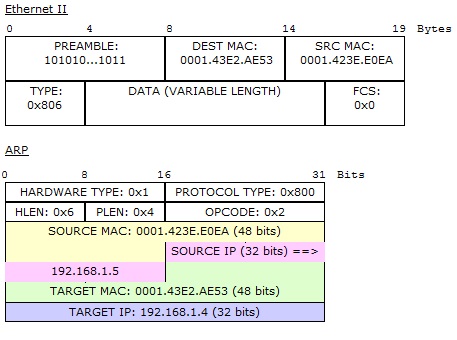
The ARP request`s target IP (192.168.1.5) got matched with 192.168.1.5, so this host will reply to PC2, so the magic that happens next is:


The address has been resolved to corresponding MAC address as can be seen in Out Layers, so in the last stage:


As you can see in above ARP packet at the source host PC2, the pinged L3 address of PC4 has been successfully resolved to its corresponding MAC (Hardware) address. Packet tracer is one of the best tools to see all the action on data packets in a real time network. To check ARP table on a router, use show ip arp command.


ARP due to is its open nature is susceptible to attacks. The most common attack on ARP packets is ARP Spoofing or Man in the middle attack. In such an attack, a hacker responds to ARP requests in disguise of the requested L3 address. One most recent example of ARP spoofing attack was carried out by Iran on an American drone, which was hacked and landed in Iran by Iranian Defense forces. Same sort of experiment was carried out in a US University in which ARP spoofing was used as an attack mechanism on Drones, and it was quite successful. DOS (Denial of Service) attack can be carried out very easily on the electronics devices which are using ARP stuffing, so a hacker can easily jam all the surveillance system of some big corporation J


Some addition NAT Services


We can adjust timeout values for different sort of packets in NAT is follow:


Some special NAT services that we can enable are for SIP and other communication protocols:


These services are needed to be enabled as we can’t modify IP header value in data packet in some special applications SIP, H.323 etc.


SNAT: Statefull Network Address Translation:

Okay, no network is ideal when it comes to 100 % up time, to avoid network failure; we use redundancy in our designs. So how it’s done in NAT? For this purpose we use Statefull NAT. in SNAT we create a group of our NAT IP addresses. The active Translator IP continuously exchanges the route maps and NAT entries with the Redundant NAT IP, in case the active IP translator fails, the redundant IP Translator take charge immediately. It is better represented in below network Topology:


I think that’s enough! We have had quite a discussion on NAT. NAT is one of the coolest protocol, which has really helped in preservation of the IP address space. If there was no NAT, we would be using IPv6 now!

 A little recap of what we have discussed so far:

  • Dynamic NAT
  • Static NAT
  • Dynamic NAT with PAT
  • Practical implementation of NAT-3 Steps
  • NAT Debugging
  • NAT translation timeout control
  • Common issues with NAT and its troubleshooting
  • NAT special services
  • SNAT or Statefull NAT

I would request you to please implement the above mentioned NAT topologies and practice all the NAT related configurations. As Practice is the key to master NATING! 


Network Address Translation V


In this part of NAT we will discuss the last common type of NAT, which is Static NAT. we will also discuss some of the features and special services on NAT. The discussion ends with a brief overview of SNAT (state-full Network Address Translation)

Static NAT:

Now let’s suppose we have our email server on 192.168.4.1/24 on R1. Suppose we want to create a static NAT entry to for SMTP (simple mail transfer protocol) on this server, so that it can communicate with the outside world and its SMTP service should be accessible from outside as well.

 It is achieved by enabling Static NAT on R2; we just need to issue the following command in global configuration mode:

ip nat inside source static tcp 192.168.4.1 25 interface Serial1/0 25


Port 25 = SMTP port or email server port

On Port 25 if any packet is received on our Router R2 interface serial 1/0, it will be forwarded to our SMPT server 192.168.4.1 and vice versa.  So if we see our NAT translations, we will see a permanent static NAT entry for TCP port 25 in it:


This entry will not expire from the NAT table after translation timeout.  All dynamic entries are deleted from the NAT translation table after translation timeout. As we have already discussed, static mapping is mostly use for server accessibility from outside the local network. 
Please remember, STATIC NAT is both way NAT i.e. we can use it for accessibility from outside our network.


Troubleshooting NAT:

Some of the points we need to keep in mind while troubleshooting NAT:

  • Check they dynamic pools, they must contain correct IP ranges.
  • Check if static IPs are overlapping with the IP pool configured.
  • Check if ACL is correctly defined. The addresses to be mapped are properly specified no address left out.
  • Proper inside/outside NAT interfaces are configured.
 -- to be continued --

Network Address Translation IV


In this part of our NAT discussion, we will implement NAT with overload or PAT (Port Address Translation) on our R2 router.

NAT Overload (PAT):

Now we are going to implement NAT overload on R2, so we need to add overload to the end of ip nat command like:

First we will clear all IP NAT translations (that were done previously once we configured dynamic NAT), by issuing the following command:

R2#clear ip nat translation *

Now we will overload the NAT by using overload key word at the end of our dynamic NAT command:

R2(config)#ip nat inside source list NAT_IPs pool Global_IP_Pool overload

To check our NAT in action, we will issue some of pings from our loop back interfaces on R1:

R1#ping 171.16.10.2 source 192.168.3.1
Successful!

R1#ping 171.16.10.2 source 192.168.3.1
Successful!

R1#ping 171.16.10.2 source 192.168.2.1
Successful!

R1#ping 171.16.10.2 source 192.168.4.1
Successful!

All of these pings were successful via NATing, to check the NAT translations on R2, we will use the following commands:

R2#show ip nat translations

//some of the output omitted//


icmp 171.16.10.53:4    192.168.2.1:4      171.16.10.2:4      171.16.10.2:4
icmp 171.16.10.53:3    192.168.3.1:3      171.16.10.2:3      171.16.10.2:3
icmp 171.16.10.53:5    192.168.4.1:5      171.16.10.2:5      171.16.10.2:5


PAT can be seen in action, in below output of show ip nat translations command:

R2#show ip nat translations

/// some of the part omitted//

udp 171.16.10.53:49157 192.168.2.1:49157  171.16.10.2:33437  171.16.10.2:33437
udp 171.16.10.53:49158 192.168.2.1:49158  171.16.10.2:33438  171.16.10.2:33438
udp 171.16.10.53:49159 192.168.2.1:49159  171.16.10.2:33439  171.16.10.2:33439
udp 171.16.10.53:49164 192.168.2.1:49164  171.16.10.2:33437  171.16.10.2:33437
udp 171.16.10.53:49165 192.168.2.1:49165  171.16.10.2:33438  171.16.10.2:33438
udp 171.16.10.53:49166 192.168.2.1:49166  171.16.10.2:33439  171.16.10.2:33439
icmp 171.16.10.53:10   192.168.3.1:10     171.16.10.2:10     171.16.10.2:10

if we want to check NAT in real time, all the action can be seen via bebug ip nat command on R2:
Once debug command is issued on R2, all the IP changes happening in real time can be seen as on R2 as follow:

R2#
*Mar  1 00:07:31.079: NAT: [0] Allocated Port for 192.168.2.1 -> 171.16.10.53: wanted 6 got 6
*Mar  1 00:07:31.083: NAT*: i: icmp (192.168.2.1, 6) -> (171.16.10.2, 6) [30]
*Mar  1 00:07:31.087: NAT*: i: icmp (192.168.2.1, 6) -> (171.16.10.2, 6) [30]
*Mar  1 00:07:31.087: NAT*: s=192.168.2.1->171.16.10.53, d=171.16.10.2 [30]
*Mar  1 00:07:31.115: NAT*: o: icmp (171.16.10.2, 6) -> (171.16.10.53, 6) [30]
*Mar  1 00:07:31.115: NAT*: s=171.16.10.2, d=171.16.10.53->192.168.2.1 [30]
*Mar  1 00:07:31.147: NAT*: i: icmp (192.168.2.1, 6) -> (171.16.10.2, 6) [31]
*Mar  1 00:07:31.147: NAT*: s=192.168.2.1->171.16.10.53, d=171.16.10.2 [31]
*Mar  1 00:07:31.179: NAT*: o: icmp (171.16.10.2, 6) -> (171.16.10.53, 6) [31]
*Mar  1 00:07:31.179: NAT*: s=171.16.10.2, d=171.16.10.53->192.168.2.1 [31]
*Mar  1 00:07:31.191: NAT*: i: icmp (192.168.2.1, 6) -> (171.16.10.2, 6) [32]
*Mar  1 00:07:31.191: NAT*: s=192.168.2.1->171.16.10.53, d=171.16.10.2 [32]
*Mar  1 00:07:31.211: NAT*: o: icmp (171.16.10.2, 6) -> (171.16.10.53, 6) [32]
*Mar  1 00:07:31.211: NAT*: s=171.16.10.2, d=171.16.10.53->192.168.2.1 [32]
*Mar  1 00:07:31.219: NAT*: i: icmp (192.168.2.1, 6) -> (171.16.10.2, 6) [33]
*Mar  1 00:07:31.219: NAT*: s=192.168.2.1->171.16.10.53, d=171.16.10.2 [33]


All this action will be seen if we issue some connectivity commands from other routers, whose packets are going through R2. It’s one of the best way to check and troubleshoot different NAT issues. Please remember, PAT (Port Address Translation) is a one way NAT, we can’t use it as a both way NAT solution.
 -- to be continued --